UEI Europe Office
+49 40 63698136
Email EU Sales
General
(508) 921-4600
Email Sales
Email Support
Click here for local offices and distributors.
QUICK LINKS | ||
 |  |  |
 |  |  |
 | ||
MIL-STD-1553 is a military standard that defines mechanical, electrical, and operating characteristics of a serial data communication bus for the U.S. Department of Defense. It is now commonly used for both military and civilian applications in avionics, aircraft, and spacecraft data handling. A 1553 system typically uses a dual redundant, balanced-line, physical layer with a differential network interface with time division multiplexing, half-duplex, command/ response data communication protocol with up to 32 remote terminal devices. It was first used in the F-16 fighter aircraft and is now widely used by all branches of the U.S. military and NATO.
For more information about MIL-STD-1553, watch the following videos.
MIL STD 1553 Overview video
Complete 1553 Solution
The current standard, MIL-STD-1553B was introduced in 1978, the goal of which was to define explicitly how each option should function, so that compatibility among manufacturers could be guaranteed.
MIL-STD-1553 is the military’s equivalent to ARINC-429, though structurally it is VERY different. The first and most obvious difference is that most 1553 links are designed with dual, redundant channels. Though commercial aircraft don’t typically get wires cut by bullets or flak, military aircraft are typically designed such that a single cut wire or wiring harness won’t cause a loss of system control. If you are looking to “hook” to a MIL-1553 device, be sure your interface has both channels.
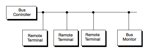
Also, a MIL STD 1553 device can serve as Bus Controller, Bus Monitor, or Remote Terminal. Not all interfaces support all three functions. Be sure the interface you select has the capability you require.
As with the ARINC-429 bus, when operating as a bus controller, the unit must be capable of detailed transmission scheduling (including major and minor frame timing) and this is best per- formed in hardware rather than via software timing.
A single 1553 bus consists of a shielded twisted-wire pair with 70 - 85 ohm impedance at 1 MHz. If a coaxial connector is used, the center pin is used for the high Manchester bi-phase signal. All transmitter and receiver devices connect to the bus either through coupling transformers or directly through stub connectors and isolation transformers, as shown below. Stubs can be a maximum of 1 foot in length for direct coupling or a maximum of 20 feet for transformer coupling. To limit reflections, the data bus must be terminated by resistors equal to the cable characteristic impedance (within ±2%). The below image shows one of the two buses. Each transceiver is also connected in the same way to the second (redundant) bus. Our 1553 IO board has 2 channels. Each channel is an independent 1553 System that supports Bus A and Bus B.
 | UEI’s DNx-1553-553 MIL-STD-1553 I/O board features 2 Independent and dual redundant bus interfaces, BC/RT/MT modes, Multiple RT simulation up to 32 RTs, Supports 1553A or 1553B protocols (including notice 2), and Transformer or Direct Coupling. Click here to learn more. |
All 1553 messages on the bus contain one or more 16-bit words, classified as command, data, or status word types. Each word is preceded by a 3 ms sync pulse and is followed by an odd parity bit. Note that since the sync pulse — 1.5 ms low followed by 1.5 ms high — cannot occur in a Manchester code, it is therefore unique. The words in a message are transmitted with no gap between words, but a 4 ms gap is inserted between successive messages. All devices must start transmitting a response to a command within 4 to 12 ms. If they do not start transmitting within 14 ms, they are considered to have not received the command message.
A typical system is illustrated below.
The 1553 standard defines three word types:
Each word type has a specific format within a common structure. All words are 20 bits in length and the first three bits are a synchronization field, which enables the decoding clock to re-sync at the beginning of each new word. The next 16 bits contain the information, in a format that varies with the word type. The last bit in the word is a parity bit, which is based on odd parity for a single word.
All bit encoding is based on bi-phase Manchester II format, which provides a self-clocking waveform. The signal is symmetrical about zero and is therefore compatible with transformer coupling.
In Manchester coding, signal transitions occur only at the center of a bit time. A logic “0” is defined as a transition from negative to positive level; a logic “1” is the reverse. Note that the voltage levels on the bus are not the information signal; all information is contained in the timing and direction of the zero crossings of the signal on the bus.
The terminal hardware provides the encoding and decoding of the various word types. The encoder also calculates parity. For received messages, the decoder signals the logic what sync type a word is and whether or not parity is valid. For transmitted messages, input to the encoder defines what sync type to place at the beginning of a word. The encoder calculates parity automatically for each word.
The formats for each word type are illustrated below.
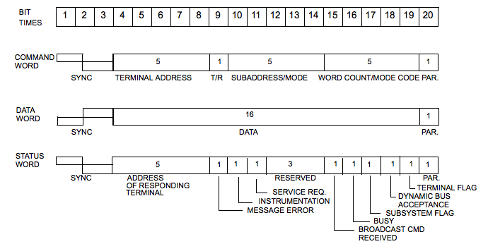
A Command Word format uses the first 5 bits for the address of the Remote Terminal (0 to 31). The sixth bit is 0 for Receive and 1 for Transmit. The next 5 bits indicate the subaddress/mode code bits. If this field is a 00000B or 11111B, the command is a Mode Code Command. All other bits direct the data to specific functions in the subsystem. The next 5 bits define the Word Count or Mode Code to be performed. If this field is 00000B or 1111B, the field defines a mode code to be performed. If it is not, the field defines the number of data words to be transmitted or received (depending on the T/R bit). A word count field of 00000B means 32 data words.
The last bit is word parity. Only odd parity is used.
A data word contains the information being transferred in a message. The first 3 bit times contain a data sync, which is opposite to that used for a command or status word.
Data words can be transmitted by either a remote terminal (transmit command) or a bus controller (receive command). The remote terminal is the reference point.
The next 16 bits may be used however the designer wishes. The only standard requirement is that the most significant bit must be transmitted first.
The last bit is an odd parity bit.
A remote terminal responds to a valid message by transmitting a status word. The status word tells the bus controller whether or not a message was received properly and what the state of the terminal is.
The status word is cleared after receiving a a valid command word. After the status word is cleared, the bits are set again if the conditions that set the bits initially still exist. If an error is detected in the data, the Message Error bit is set and transmission of the status word is suppressed. Transmission of the status word is also suppressed whenever a broadcast message is received.
The first 5 bits of the status word (bits 4-8) are the Terminal Address. The remote terminal sets these bits to the address to which it has been programmed. The bus controller examines these bits to ensure that the responding terminal is the one to which the command word was addressed.
The next bit (9) is the Message Error bit, which is set by the terminal on detection of an error or an invalid message. Whenever this bit is set, none of the data received in the message is used. When an error is detected, the remote terminal must suppress transmission of the status word.
The Instrumentation bit (10) differentiates a command word form a status word (both have the same sync pattern). The instrumentation bit in a status word is always set to ”0”. When used, the instrumentation bit in a command word is always set to “1”. Since this bit is the most significant bit of the subaddress field, using it as an instrumentation bit reduces the number of available subaddresses from 30 to 15. Because of this limitation, most systems today use techniques other than the instrumentation bit to differentiate between command and status words.
The Service Request bit (11) enables a terminal to inform the bus controller that it needs to be serviced. A “1” in this bit indicates that service is needed. It is typically used when the bus controller is polling the terminals.
Bits 12 - 14 are reserved for future use and must be set to “0”. Any other value is an error.
A “1” in Bit 15 indicates that the terminal received a valid broadcast command. Whenever a terminal receives a valid broadcast command, the terminal sets this bit to “1” and suppresses transmission of its status word.
A “1” in Bit 16 (“busy” bit) tells the Bus Controller that the terminal cannot act on a command to move data between the terminal and subsystem. This bit is typically not used in modern system designs and is discouraged by Notice 2 of the standard.
A “1” in Bit 17 is used as an indicator of existence of a fault in a subsystem. A “1” in Bit 18 indicates that the remote terminal has received a mode code and has accepted control of the bus. After setting this bit, the remote terminal becomes the bus controller.
A “1” in Bit 19 (the Terminal Flag) indicates to the bus controller that a fault exists in the remote terminal hardware.
Watch the following videos for more information.
Injecting Errors Into the Traffic On the Bus
Injecting Errors Into the Status Word
Any device that is not a Bus Controller or a Bus Monitor is, by definition, a Remote Terminal.
A Remote Terminal can be used as an interface between the bus(es) and a subsystem or as a connector between this bus and another 1553 bus. A subsystem is the sender or user of the information transferred on the bus. A remote terminal contains all the components needed to transfer the data from the sender source to the destination user.
The Bus Controller (BC) manages the flow of data on the buses. Only one bus controller can be active at a given time. A bus controller may be one of three types: (1) Word Controller, (2) Message Controller, or (3) Frame Controller.
A Word controller, which handles one word at a time, is seldom used today because of the processing burden it places on the subsystem.
A Message Controller handles one message at a time, interacting with the computer only when a message is complete or when a fault occurs.
A Frame Controller can process multiple message in a defined sequence, interrupting the computer only when the message stream is complete or after an error is detected.
Watch the following video for more information.
A Bus Monitor is not able to transmit messages on the bus; its function is to monitor, and record, messages being transmitted on the bus without disrupting other devices. A bus monitor can be set up to record selected subsets of the messages on the bus. It can also be set up as a backup bus controller, ready to take over whenever needed.
Watch the following video for more information.
Each IO board has 2 channels. Each channel is a complete 1553 system with Side A and Side B. Each channel can be configured as a BC, RT or MT. You can also add a MT to a BC or RT channel. The MT does not change the BC or RT functionality. The MT simply allows you to see what is on the bus for any specified RT or all Bus Traffic.
UEI customers can use a variety of programming languages to access the full functionality of our MIL-STD-1553 components, but, to help get the data they need quickly, we’ve created a graphical utility we call PowerDNA Explorer. This video shows you how easy it is to set up and use.
UEI hardware is designed to be software flexible which means it works with a variety of different languages and programs including National Instruments' LabVIEW.
High-speed, precise timing on a UEI MIL-STD-1553 I/O board is not determined by the API you use but by the FPGA on the board itself.
| The Common Aircraft Armaments Test Set (CAATS) is the replacement for the 25-year old Common Rack and Launcher Test Set (CRALTS) and will be the new standard to test today’s smart armament systems. This sophisticated system is designed with United Electronic Industries (UEI) hardware and I/O solutions that offer ruggedness, I/O flexibility and longevity. UEI Products used in CAATS: |
UEI has a wide variety of solutions for your defense and aerospace applications. Please click on the below to learn more.
 |  |  |  |