General
(508) 921-4600
Email Sales
Email Support
UEI Europe Office
+49 40 63698136
Email EU Sales
Visit this page for local offices and distributors.
QUICK LINKS | ||
 |  |  |
 |  | |
 |  |  |
Mechanical flight was simple – pilots would grab a joystick or step on a pedal and a system of rods, cables, and pulleys would slide, twist, and turn to control the movements of the aircraft. Today’s fly-by-wire aircraft are a bit more complex. Various electronic equipment must be able to work together to monitor fuel amounts, navigate the sky, detect weather patterns, and everything else associated with successful flight. Now what happens when a Boeing 737 replaces an air data computer with a different manufacturer? Will the new equipment will be able to communicate with the rest of the aircraft?
ARINC-429 defines the standard requirements and protocols for the transportation of digital data between avionic systems in commercial aircraft. These standards are followed by equipment manufacturers, enabling the interchangeability of avionics equipment.
Watch the following video and continue reading to learn more about the ARINC-429 specifications and characteristics.
The ARINC-429 technical specification, originally referred to as the Digital Information Transfer System (DTIS), was published in 1977 to define how avionics systems and components should communicate within commercial aircraft. The Mark 33 Digital Information Transfer System, as it is known today, is still the standard most commonly used by airlines. This specification is used to establish 429 bus communications for word structures, electrical characteristics and other protocols.
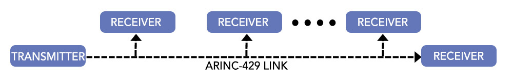
What is unique about ARINC 429 data transfer is its simple one directional flow of bus communications data. A typical data bus offers multidirectional data transfer between various bus points on a single set of wires. Not so with ARINC-429, but this is not taken as a disadvantage to the airlines as it has allowed for long-term operational cost savings and system reliability.
The ARINC-429 specification entails the following:
You will learn more about word formats and transmission below.
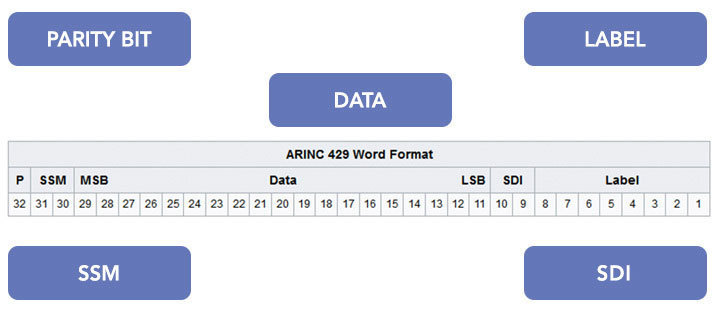
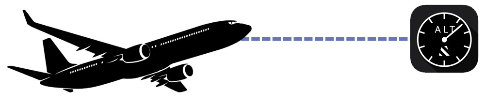
Data is sent over the ARINC-429 bus in a 32-bit word, with each word representing an engineering unit such as altitude or barometric pressure. The different parts of the message are shown in the image above. The 8-bit label is an important aspect. It is used to interpret the other fields of a message – each type of equipment will have a set of standard parameters identified by the label number, regardless of the manufacturer. For example, Label 372 for any Heading Reference system will provide wind direction and Label 203 for any air data computer will give barometric altitude.
The other bits are reserved for SDI, SSM, data, and parity:
True testing of avionics systems occurs after the known good cases are run. If everything works, that’s great, but what does your system do when things are not right? You need the ability to change any field in a 429 message so that it is NOT correct: you need to be able force a parity error; have out of bounds data for a particular label; and change the SDI and or SSM at will.
While UEI’s ARINC-429 allows users to simulate a complete and fully functioning 429 system, UEI also provides you the ability to inject errors to fully test your system’s real world error handling capabilities. Learn more about the 429 solutions below:
| UEI’s DNx-429-516 I/O board features 16 ARINC 429 RX or TX plus 8 dedicated RX channels, high (100 kHz) or low (12.5 kHx) speed selectable by channel, hardware label filtering and TX scheduler, and includes support for ARINC-615 protocol. Click here to learn more. | |
| UEI’s DNx-429-512 I/O board features 12 ARINC 429 RX channels, high (100 kHz) or low (12.5 kHz) speed selectable by channel, hardware label filtering, automatic timestamping of RX data, and includes a powerful API. Click here to learn more. | |
| UEI’s DNx-429-566 I/O board features 6 ARINC 429 TX and RX channels, high (100 kHz) or low (12.5 kHz) speed selectable by channel, hardware label filtering and TX scheduler, automatic timestamping of RX data, includes a powerful API, and can support ARINC 615 as well. Click here to learn more. |
Data is transmitted in a Return-to-Zero (RZ) format with three different states – HIGH(1), NULL, and LOW(0). HIGH state is achieved when the transmission signal jumps from NULL to +10V, then back to zero. LOW is similarly achieved when the signal goes to -10V and back.
ARINC 429 specifies two speeds for data transmission – low speed of 12.5 kHz with an allowable range of 12 to14.5kHz, and a high speed of 100kHz +/- 1%. While this may be fair for most cases, some systems require a bit more flexibility.
UEI enables our customers to adjust the standard transmissions speeds by 33%, allowing the testing of a variety of different systems and setups. This is a tool you need to get the job done in the real world and is also useful for design verification of your avionics.
Typical update rates are set to either 25, 40, or 65 ms. Avionics equipment usually display inoperable after two consecutive frames are missing, which can be strenuous on the software that is running. To ensure consistent messaging success, it is best practice to have the hardware help save the software’s bandwidth. The two types of messaging techniques are First-in First-out (FIFO) and the Scheduler.
 |
As mentioned above, if you need to send a message, you can use one or both methods:
You can have messages sent at 3 different frequencies and set for a time delay so a message has different timing than the previous message. You can also be notified if a command was sent as well as have a message be sent once and only once if needed.
For successful real-world ARINC 429 testing, you should have a flexible, capable scheduler.
Both the FIFO and Scheduler are further explained in detail in the video below:
Testing, verifying, simulating, and controlling avionics busses present many challenges.
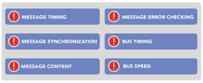
UEI offers a wide variety of methods to control and verify avionic equipment so your systems run efficiently.
UEI has developed special features for ARINC 429 to solve critical operational challenges:
Precise Timing - A client needed to be signaled upon receipt of a GPS label. They could do it in software, however timing was an issue. UEI's solution was to use the FPGA for precise timing. In one application, a non-ARINC 429 device need to know when a label was sent. We adapted the system to send a pulse when a label of a particular value was transmitted.
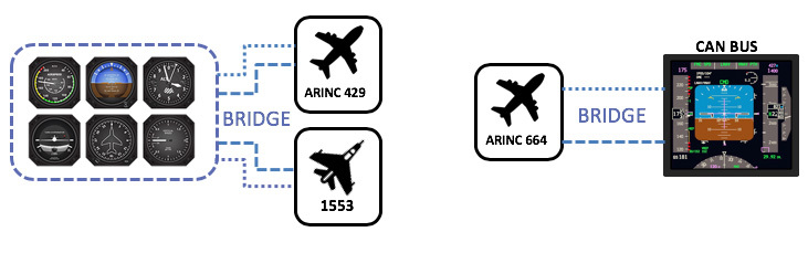
Bus Conversion - Many times, protocols need to be converted. With a 1553 and 429 IO board, one application took in 1553 and send it out 429. Another took in ARINC 664 (AFDX™) and sent the data out in a CAN bus. In flight, a new entry into the Very Light Jet Market required a single Data Acquisition System that not only monitors the analog and digital inputs but also ARINC-429 avionics bus, RS-232 devices with an integrated GPS receiver to log position and velocity data. UEI was able to provide this solution.
 | A new entrant in the field of VLJ (Very Light Jets) and an established market leader in the design and manufacture of business jets have very similar requirements. Both needed to build a data logger into their aircraft that will monitor a wide variety of systems within the vehicles. The application requires a compact, rugged, 24 VDC powered logger that not only monitors the analog and digital inputs normally associated with data logging. Learn how UEI provided the ideal solution. |
 | The pulse of an avionics system is the data. In this Webcast, you will learn how to interface to many industry standard specifications, such as ARINC-429, ARINC-664, MIL-STD-1553, and Serial, using one system and one API to obtain vital mission-critical data. Whether you are exercising a LRU or just monitoring the data on a 1553 bus, the techniques showcased in this webcast detail ways to not only store but visualize, convert and export avionics data using standalone or networked configurations. |
UEI has a wide variety of solutions for your defense and aerospace applications. Please click on the below to learn more.
 |  |  |  |