General
(508) 921-4600
Email Sales
Email Support
UEI Europe Office
+49 40 63698136
Email EU Sales
Visit this page for local offices and distributors.

QUICK LINKS | ||
 |  |  |
 |  |  |
Synchro: Transducer that uses a transformer whose primary-to-secondary coupling may be altered by changing the relative orientation of the two windings. Synchros are often used for measuring the angle of a rotating machine or in case of selsyn (self-synchronous) configuration, used for controlling position of a device. In its general physical construction, it is much like an electric motor. The primary winding of the transformer, fixed to the rotor, is excited by an alternating current causes voltages to appear between the Y-connected secondary windings fixed spatially at 120 degrees to each other on the stator. The voltages are measured and used to determine the angle of the rotor relative to the stator.
Resolver: Type of rotary electrical transformer used for measuring degrees of rotation. The name resolver comes from resolving an angular input in to its x and y components. It is considered an analog device, and has digital counterparts such as the digital resolver, rotary (pulse) encoder.
What to know about common misconceptions of synchro signals? Click to read the blog post below.
UEI manufactures a wide variety of analog and digital IO boards, including ones for Synchro/Resolvers, LVDTs, and RVDTs. Each board can supply the excitation voltage and measure the output wave forms of the transducer. They can also be used in simulation applications to simulate the transducer.
Like all UEI IO Boards, the Synchro/Resolver IO Board offers operation in harsh environments and has been tested to last within:
Synchro/Resolvers allow you to monitor and control:
Engineers use UEI hardware to test, measure and control synchro, resolver, and VDTs for their applications. Our versatile IO boards can support Star or Delta configurations as well as a wide range of voltages and frequencies.
There are two types of synchro systems: torque systems and control systems.
Torque system: a system in which the transmitted signal does the usable work. In such a system, accuracy on the order of one degree is attainable.
Control system: a synchro will provide a voltage for conversion to torque through an amplifier and a servomotor. Control type synchros are used in applications that require large torques or high accuracy such as follow-up links and error detectors in servo, automatic control systems (such as an autopilot system). In simpler terms, a control synchro system is a system in which the transmitted signal controls a source of power which does the usable work.
We have designed our data acquisition hardware to be software flexible. That means you can use a variety of programming languages and programs with our UEI I/O boards. One particularly popular program used is National Instrument’s ‘LabVIEW’. We supply these samples so you can create a standard acquisition application in the shortest time possible. UEI supports a variety of acquisition modes (Buffered IO, Simple IO, Messaging IO, DMap IO) which can be accessed through the simple pull downs.
Our extensive collection of prebuilt examples and VIs make it easy to get up and running quickly. Our LabVIEW interface has the same API as our C API, which means that there are no islands of programmers at your facility. Your LabVIEW and C programming teams can exchange knowledge and experience seamlessly.
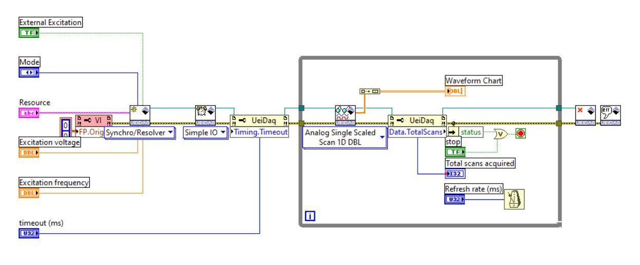
As you can see, there are simple drop downs which will allow you to configure your system to whatever specifications you would like; whether that be changing the data value you are recording or changing the method of acquiring such data.
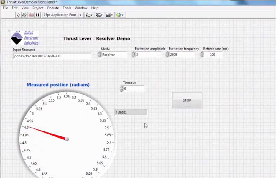
Here is a demo of a throttle system in which the position of the throttle is being measured by the resolver and relayed into a LabVIEW application.
Board | Input Range | Simulation Range | ||
Voltage | Frequency | Voltage | Frequency | |
2-28Vrms | 50Hz-4kHz | up to 28Vrms | 50Hz to 4kHz | |
5-115Vrms | 50Hz-4kHz | up to 28Vrms | 50Hz to 4kHz | |
2-28Vrms | 50Hz-10kHz | up to 19.8Vrms | 50Hz-10kHz | |
Using a different device to measure position or velocity? Check out some of these boards:
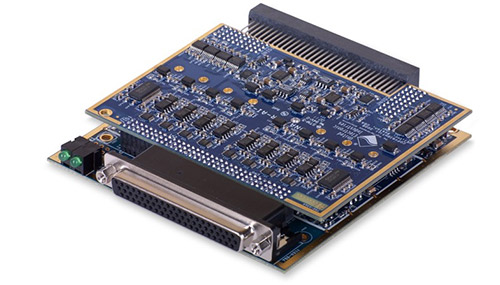
UEI offers a wide variety of Synchro/Resolver I/O boards, available for cube, rack, or military chassis, and are well suited for test, measurement, control, and simulation applications.. All UEI I/O boards offer operations in harsh environments and has been tested to 5g vibration, 50g shock, -40 to +85°C temperature, and altitudes up to 70,000 feet in cube based systems. Each board is capable of supplying the excitation voltage and measuring the output waveforms of the transducer. They can also be used in simulation applications to simulate the output of the transducer.
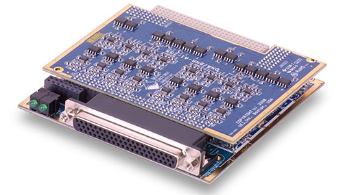 | The DNx-AI-255 Synchro/Resolver I/O board features 2 input / output channels, 16-bit resolution, 3-wire (Synchro) and 4-wire (Resolver) inputs, reference output per channel, 2 to 28 Vrms programmable reference, 50 Hz to 4000 Hz, 28 Vrms output at 1.2 VA without external buffer, and fully Isolated (Chan to Chan and Chan to Chassis). Click here to learn more. |
 | The DNx-AI-255-815 Synchro/Resolver I/O board features 2 input / output channels, 16-bit resolution, 3-wire (Synchro) and 4-wire (Resolver) inputs, reference output per channel, 5-115 Vrms inputs, 50 Hz to 4000 Hz, 2-28 Vrms output/reference at 1.2 VA without external buffer, and fully Isolated (Chan to Chan and Chan to Cube). Click here to learn more. |
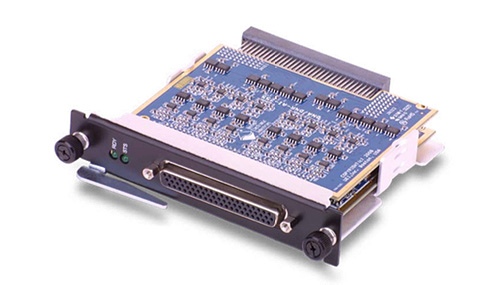
 | The DNx-AI-256 High Output Drive Synchro/Resolver/LVDT/RVDT board features 2 input / output channels, 16-bit resolution, 3-wire (Synchro) and 4-wire (Resolver) inputs, 4, 5 and 6-wire LVDT/RVDT support, reference output per channel, 5 to 18 Vrms programmable reference, 50 Hz to 10 kHz, and up to 2.4 VA without external buffer. Click here to learn more. |
We show you how to quickly configure LabVIEW to receive data from a United Electronic Industries Synchro/Resolver I/O module. In this example, the module is measuring the position of an aircraft thruster and passing along the data to the LabVIEW software running on a standard PC laptop.
UEI engineers demonstrate how they can use a UEI Synchro/Resolver I/O board to gather data from an aircraft thrust lever and feed it into a National Instruments LabVIEW application. This simulation can monitor the thrust position as well as capture and export the data.
Dana explains the troubleshooting process UEI's engineering team used to evaluate an erratic flap indicator using an AI-256.
UEI has a wide variety of solutions for your defense and aerospace applications. Please click on the below to learn more.
 |  |  |  |