General
(508) 921-4600
Email Sales
Email Support
UEI Europe Office
+49 40 63698136
Email EU Sales
Visit this page for local offices and distributors.

QUICK LINKS | ||
 |  |  |
 |  |  |
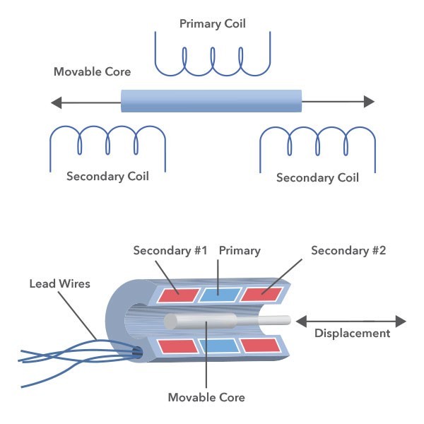
LVDT is an acronym for Linear Variable Differential Transformer. It measures absolute linear displacement. RVDT is a Rotary Variable Differential Transformer. It measures absolute rotary angle.
The RVDT has both a rotor, that is turned by external force, and an electromechanical transducer capable of outputting alternate (AC) current voltage that is commensurate to rotor shaft angular displacement. When an AC voltage is applied to an RVDT, the output voltage versus shaft angular displacement (transfer function) will be linear over a specific range of displacement. To ensure long term operation, RVDTs use contactless electromagnetic coupling and high-resolution repeatable position sensing. RVDTs are low-cost, small, reliable, and handle variations in temperature, voltage and frequency very well.
LVDTs convert linear displacement into electrical signals -- from a mechanical reference (zero/null position) to a proportional electrical signal containing phase and amplitude. These transducers are frictionless, sturdy and have great longevity. LVDTs are operated via AC voltage and do not contain electronics (does not require any electrically contact between moving parts), which allow them to be operated efficiently in harsh environments and temperatures. Operation happens through electromagnetic coupling.
Before deployment, you can test LVDT/RVDTs in simulation scenarios, as an example input versus emulator. In many cases you'll be working with existing infrastructure around in LVDT/RVDT and you'll want to simulate an LVDT/RVDT from your digital system. This is advantageous in the case that you're trying to switch from a human operated device to a computer operated device. For example, you'd want an RVDT/LVDT simulator to take in excitation and to output the secondary output. The other case is being an RVDT/LVDT input. In this case we need to provide an LVDT, a primary excitation, and be able to read back and interpret the secondary output.
Anything that needs physical positioning measurement is a good candidate.
Engineers use UEI hardware to test, measure and control synchro, resolver, and VDTs for their applications. Our versatile IO boards can support Star or Delta configurations as well as a wide range of voltages and frequencies.
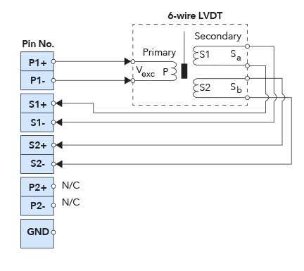
 | Check out the list of figures and diagrams in UEI's AI-254 4-Channel LVDT/RVDT Interface user manual for additional information. |
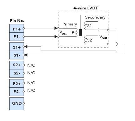
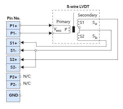
Internally Excited: With internally excited VDTs, your interfacing system needs to read in the AC voltage on the primaries and compare that to the secondary voltages.
Externally Excited: With externally excited VDTs, you need to provide an external excitation to the primaries and read it back on the secondaries.
UEI manufactures a wide variety of analog and digital IO boards, including ones for Synchro/Resolvers, LVDTs, and RVDTs. Each board can supply the excitation voltage for and measure the output wave forms of the transducer. They can also be used in simulation applications to simulate the output of the transducer. Like all UEI IO Boards, the LVDT/RVDT IO Board offers operation in harsh environments and has been tested to last within:
We have designed our data acquisition hardware to be software-flexible, which means that you can use a variety of programming languages and programs with our UEI I/O boards. UEI also supports a variety of acquisition modes (Buffered I/O, Simple I/O, Messaging I/O, DMap I/O) which can be accessed through the simple pull downs.
UEI’s prebuilt examples and VIs make it easy to get up and running quickly. The UEI LabVIEW interface has the same API as the UEI C API, which means that there are no islands of programmers between groups. Your LabVIEW and C teams can exchange knowledge and experience.
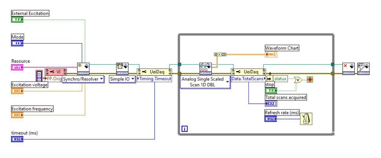
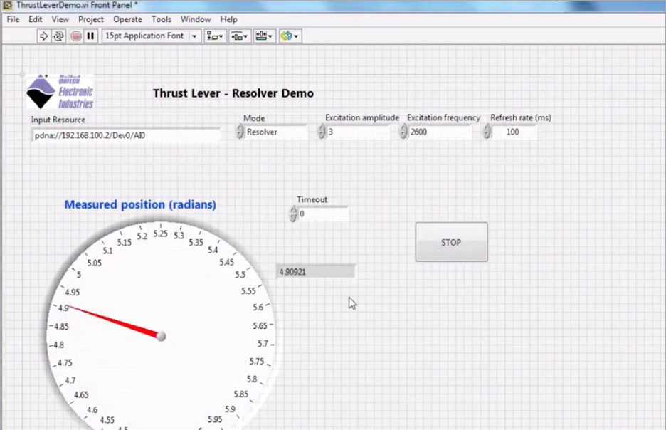
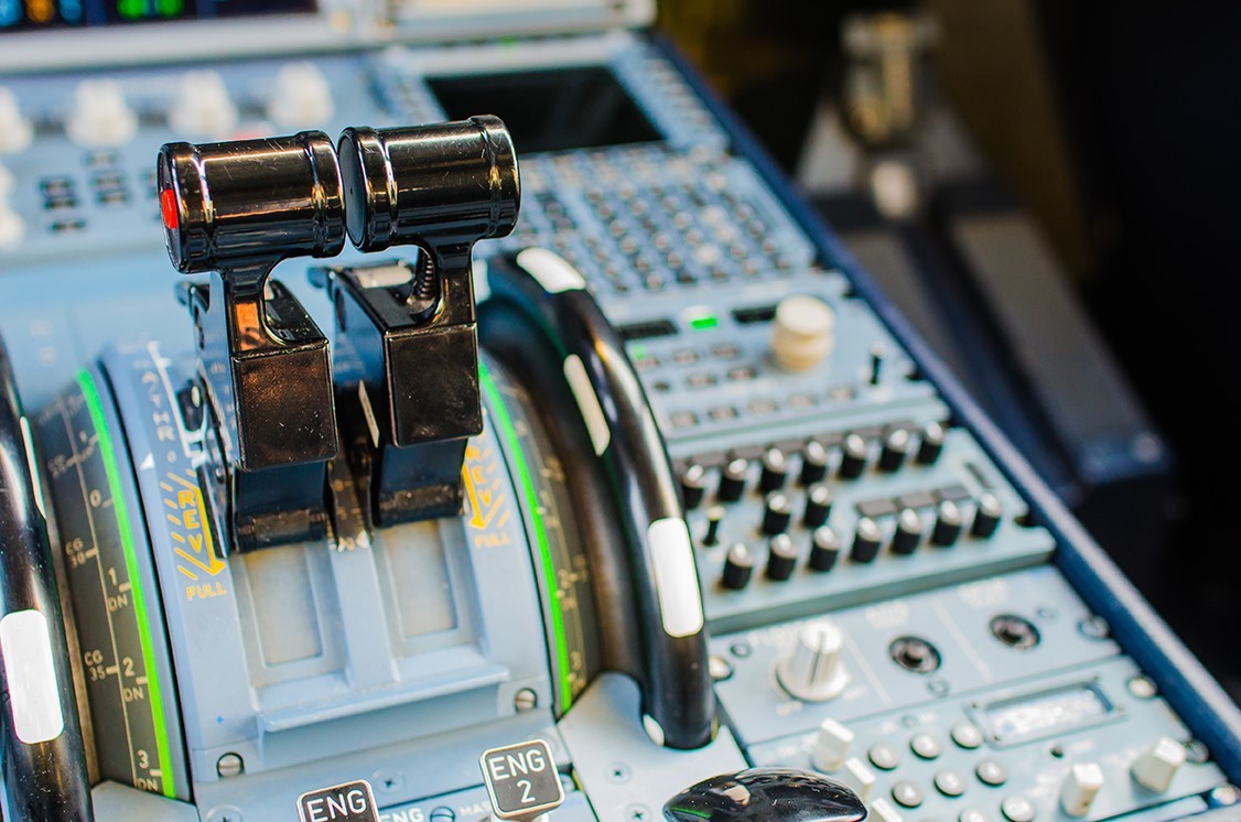
Here is a demo of a throttle system in which the position of the throttle is being measured by the resolver and relayed into a LabVIEW application.
Board | Input Range | Simulation/Excitation Range | ||
Voltage | Frequency | Voltage | Frequency | |
2-28 Vrms | 100 Hz-5 kHz | Up to 6.7 Vrms in 4-wire and 6-wire mode | 1-3.35 Vrms in 5-wire mode | 100 Hz to 5 kHz | |
2-28 Vrms | 50 Hz-10 kHz | Up to 19.8 Vrms | 50 Hz-10 kHz | |
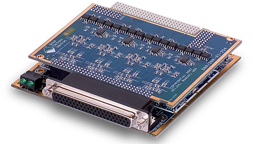 | The DNx-AI-254 is a four channel LVDT/RVDT input and output simulation board for UEI's powerful data acquisition and control chassis. The boards are ideally suited for a wide variety of rotational and linear motion measurements in many industries. The boards also offer a unique LVDT/RVDT simulated output capability designed to provide stimulus in avionics test and simulator applications. Each of the four channels on the board may be configured as either an input channel with excitation or as an output/simulator. |
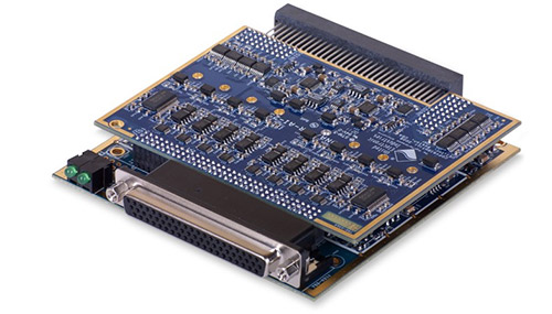 | The DNx-AI-256 High Output Drive Synchro/Resolver/LVDT/RVDT board features 2 input / output channels, 16-bit resolution, 3-wire (Synchro) and 4-wire (Resolver) inputs, 4, 5 and 6-wire LVDT/RVDT support, reference output per channel, 5 to 18 Vrms programmable reference, 50 Hz to 10 kHz, and up to 2.4 VA without external buffer. |
Using a different device to measure position or velocity? Check out some of these boards:
Our lead design engineer demonstrates how he can use a four channel LVDT/RVDT I/O board to read the output from an aircraft thrust level and display the changes in real-time via onboard web server. The board also outputs the pulse width modulation signal to control lamps.
LVDTs and RVDTs are robust, theoretically infinitely precise positioning devices. These devices are used everywhere from the thrust levers on fighter jets to cryogenics labs. The UEI Applications Group will cover how these devices work, and how to interface with them using our DNx-AI-254 LVDT/RVDT Interface Board. We will also take this opportunity to demonstrate both the Low-Level C-API and the High-Level Framework API. Whether it is C, C++, Python, or a wide array of .NET languages, we show the flexibility of these languages on our hardware.